5Digits on shortblocks,
cylinder heads & intake manifolds...
(information on porting, coolant flow, Neon heads, EGR valves, etc..)
On cylinder head porting:
I have seen modern cars without turbos actually slow down from port and flow work...A guy I know had his ram 360 PU running mid 14s...he spent about $1000 on his head and it slowed the truck down to the low 15s!
It is easier to destroy a cylinder head than it is to make progress. Typically a good cylinder head job will produce positive results. But when velocity and low lift efficiency is replaced with volume and high lift flow - The peak flow increases but the "area under the curve" will be lost. What this means is that peak flow, at peak lift, only happens for an instant, when compared to the flow from when the valve opens to when the valve closes. This is where peak flow numbers lose there value.
It seems that most modern EFI cars that are nonturbo slow down with lots of flow work....they like speed and efficiency of flow compared to mass of flow....
Yes, when the calibration is not adjusted accordingly.
Our turbos (except turbo 1s) like port work.....I had a big valve head bilt with lots of flow work....cc'd to stock..... my T1 would not even run with it on......tried everything....but when the car was converted to a T2 with T2 electronics it liked it!
The old TI electronics were very crude. From knock sensor operation to fuel and spark - Many improvements were made, from model year to model year. The fact that the electronics/software were in their infancy stage and the T-I injectors were very small - Probably made for good knock/spark retard conditions (Loss of power). If poor idle quality was present, it could have been attributed to the non-heated sensor and the early calibration/poor accuracy of that control system. Some of this was corrected in the Turbo-II system and would support the reason for the new found gains.
In addition, any vehicle that receives extensive hardware upgrades should have a re-calibration (SPECIFIC FOR/WITH THAT APPLICATION). This could range from fuel pressure, injectors, to a new software calibration. Careful, this is where many claims of "specifically for your car" fall short. There are too many variables that can cause variations from vehicle to vehicle. If the work was not performed in "A" specific vehicle than it is a "best guess", at best.
85 vs 86 turbo electronics...
Why won't the '85 controllers work in the '86 vehicles?
The distributor. This was done for various reasons. One of them was that the 1985 vehicles used the G-head and the 1986-87 vehicles used the fast-burn. Using an 1986-87 controller on a 1985 vehicle (equipped with a G-head) will typically result in poor performance. Although, using a 1985 controller on a 1986-87 vehicle (equipped with a fast-burn head) can be detrimental to the engine's health, IF THE APPROPRIATE PRECAUTIONS ARE NOT TAKEN. These calibrations were SPECIFIC to the head and caution should be used, if they are going to switched. For general use, make sure that the controller matches the cylinder head being used.
1985=G-head
1986-later=Fast-burn
Rich Bryant wrote: Since the distributors are different on 85/86 they definitely wont run correctly, or at all if you only swap modules (I assume this isn't what you meant).
Correct. You must keep the modules and distributors paired to achieve a functional system. The intention of original E-mail was to expose the potential issues, when this action is taken.
Why would it be a problem to put an 85 engine in an 86 car with all 86 electronics?
This
requires a close look at the heads..
G-HEAD
(in general) :
1.)
The G-head is a slow burn cylinder head with a very slow pressure rise.
2.)
The pressure rise peak is slightly less than that of a fast-burn.
3.)
A slow pressure rise will be less prone to knock.
4.)
Open chamber design = low or no swirl activity.
5.)
The combined characteristics of 1,2,3,&4 require a much more aggressive
spark schedule to get the cylinder pressures up, for throttle response
and over peak performance. This holds true on any application (i.e. N.A.,
Turbo, EFI, Carb, etc..)
FAST-BURN
(in general) :
1.)
The F.B. head is a.. well.. A fast-burn head, with a very steep and
aggressive pressure rise.
2.)
The pressure rise is not only quicker but it has a slightly higher spike
to it.
3.)
Items #1&2 makes the F.B. more susceptible to knock.
4.)
Swirl port chamber has valve-shrouding and high swirl activity.
5.)
The combined characteristics of 1,2,3,&4 require a much less aggressive
spark schedule to achieve the desired or same cylinder pressure as the
G-head. This is because the higher cylinder pressure activity is an inherent
design of the F.B. head.
Now knowing the spark is more aggressive with a slow burn head; The issues with higher spark advance on a F.B. head are identified. This scenario can be the cause of head gasket failure, cracked ring lands, melted pistons, abnormal rod bearing wear, etc..
The compression ratio is the same, but the flow would be a bit different, more low end for the 86 and more high end for the 85.
Compression ratio is the measure of static cylinder pressure. This measurement does not include or take into consideration the effects of spark advance. Adding the spark advance into the equation can result in a substantial change, in cylinder pressure. Advancing or retarding the spark advance will determine if the cylinder pressure is raised or lowered. Once again, the G-head relies on the aggressive S.A. to achieve the desired cyl. pressure. Not only is this not necessary for F.B. applications but it is typically undesired!
How is this any different than putting a ported head on the engine and running a stock module?
A definition of porting is needed here. If we are discussing a F.B. head that has been de-shrouded, then we are discussing a head that has just been de-sensitized. De-shrouding a F.B. will reduce the swirl, slow down the pressure rise, and lower the peak cylinder pressure, at the same timing value. With proper porting the flow and cylinder "packing volume" will rise. This can slightly offset the de-sensitizing effects of the chamber work. But careful.. flow volume changes are independent of combustion chamber activity. This means that the volume can be increased but the chamber can be modified in such a way that the result is still a controlled peak (spike) with a slower rise.
It would be bad to put an 86 head on an 85 bottom end since the pistons are different and would raise compression. On the other hand, many many people feel that putting an 85 G head on an 86 engine is a good thing. They want the lower compression for higher boost, and want the G head for more top end. I realize this might not be good for efficiency, but shouldn't hurt performance. (due to more boost) Various members of our community have had a great deal of success with this method.
This is all very possible but the original message was in reference to module/distributor swapping, with respect to PRODUCTION or STOCK components.
If you are correct in your statements in this area, a lot of people should change their strategies (not that they would accept it anyway) either way it is an interesting topic. If I am wrong that is fine I am not even close to an expert. It would be good to know why swapping them in each direction is bad, not just a statement that it is.
No strategy changes necessary. These posts are intended for "things to consider when doing this" information only. Knowing how the package or system will respond, ahead of time, may provide the information needed to achieve an end-result that is closer to the desired goal.
Steve Menegon wrote in: I had a conversation with Mr. Mysterious himself (5DIGITS) about making an intake that had more balance. My idea was to make a different two-piece intake that came over the top of the valve cover and center the throttle body. In essence, equal length intake runners. I thought it could be done and guess what? Ma Mopar had already done it. Here is the info 5DIGITS sent to me:
This will work!! There were several functional versions PRIOR to production release, in '84 and in '85. It worked excellent. Why didn't it make it? You're gonna LOVE this!?!
1.) Service
access to the valve train.
2.)
Crash test issues. The electronics were not as sophisticated, as they are
now. If the throttle body was broken off, in a crash, the vehicle would
essentially go to WOT. That's a problem, for production vehicles. Now there
are "safe-guards" in the code that protect against this. If the throttle
is closed, BUT airflow is at maximum, the engine goes into a fuel shut-off
routine. Ta-Dah!!
3.) Basic over-all under hood packaging. It was VERY close to the hood.
I keep looking at my T2 intake and wonder how cylinder #4 manages to get any air at all under high boost.
It does better than you think. There are alot of compounding events taking place here and they do somewhat work together.
1.) BREATHING:
#1 gets
most BUT runs the coolest (coolant). It should be richer!
#4 gets
the least BUT runs the hottest (coolant). It should be leaner!
#2&3
Well... Their trade-offs are well proportioned. Except that the #3 runner
is on the "griddle" (turbo) and receives much thinner air. So the fact
that it falls 3rd in the "air food chain" is a good thing.
I still may try to fabricate an intake like this, if I could only find the time....
2 Piece vs 1 piece intake manifold
Two piece...
Even though the 2-piece has many flaws, it is still superior to the one piece manifold. The entrance, to the runner, on a 1-piece is terrible and the neck has far less flow capability.
The 2-piece should generate stronger low end intake pulses while the better flow capabilities will improve the power above 5200. This is why the ratings on the T-II were rated at 5200RPM. After 5200 with the 1-piece... All is down hill.
Go for it! You should be rewarded.
Caution:
DO NOT
OPEN THE MATING RUNNER HOLES (where the upper and lower bolt together)
TO THE GASKET!!!!!
When
this is done a "bulb" or aneurysm is generated in the runner. This can
cancel
the tuning process of that effective area. This will effectively make the
runner appear shorter. Also the short side turn will have a high turbulent
area and flow will suffer.
I'm going to comment here since I asked this question- Mr. 5digits and myself have different philosophies regarding boost on our engine- His is to run moderate amounts of boost and make sure everything else in the induction/exhaust system flows as well as possible (hence you will need less boost to go fast). My way is to run the boost as high as needed to get the job done! The 1 piece intake is a good piece for the average joe with average parts plus injector access is a piece of cake.
The k-car has run 11.4 with a 1 piece intake using what I call the "brute force/turn the boost up" approach of making power with a turbocharger. So don't loose any sleep if your running a 1 piece intake- You would be better off getting a new turbo that wasn't based on a design penned back in 1971!!
Alexander
Melnikov quoted Vic in Phoenix: I have no tech data concerning this part
(i.e. how it goes in or
what
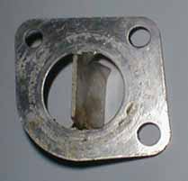
the benefits if any are) Gary's note:
they are talking about coolant redirector which goes between the waterpump
housing and the block on a Turbo III engine.
If the part in question is the T-III component, it helps redirect the coolant across the front of the block. The T-III coolant exits on the driver's side, of the head. The "path of least resistance" (coolant in the block) would be to enter the block, go to the rear of #1, turn right, travel across the back of cylinders 2, 3, and 4, and exit out the thermostat housing. This produced "coolant stagnation" and hot spots at the front of the block. The direction plate is split in the middle by a plate, with a flared tip on the back edge. This flared tip would influence coolant to make a sharp right turn, upon entry to the block. The simple part was just enough to eliminate nearly all of the stagnation and restore adequate/proper coolant flow.
Concerns: Placing this component on a 8-valve engine can cause too much of the coolant flow towards the front of the block.
With the 8-valve head, the "water-box" is in the front of the head. The normal coolant path (in the block) would be to enter the block, go to the rear of #1, turn right, travel across the back of cylinders 2, 3, and 4, turn right (towards the front of the engine), come back across the front of 4 and 3, and exit. Obviously, the coolant is being transferred into the head, throughout it's path; But a large percentage of coolant will be taking the stated routes. Too much coolant may desire to make the sharp turn and exit the block, from the front. This can generate the same T-III issue, but at the rear of the block.
If the
part is desired: If this part is desired on an 8-valve application, then
the flair/baffle size could be reduced. A rough estimation may be to reduce
the flair/baffle to approx. 10-20% of it's total size.
Please
remember to shim the bottom water pump mounting location the same thickness
of the "re-director"/coolant baffle. Using this part/these mod's, on an
8-valve head, are at your own risk.
Benefits...
unknown.
WATER PUMP: Why was the water pump rotation reversed?? A couple of reasons...
The single most important one is that it allowed for a larger impeller to be used. This raises the water pump efficiency at lower engine speeds. Water pumps are primarily designed for peak efficiency at low speeds, to generate enough/greater flow for engine cooling. The downside of this is that a larger impeller will cavitate earlier, at higher speeds. In some previous posts I have mentioned going to the older style pump, for this reason. This can really be found useful in DOHC/Lotus applications. The fan may cycle more at low speed BUT a gain in engine cooling, at high RPM, can be achieved. Owners of later model vehicles may notice that 3rd or 4th gear operation, on the highway, may yield a much higher engine temp. This is regardless of cool ambient temperatures. Utilizing the older style pump will basically achieve what an under drive pulley kit does.
Previous post on water pumps-
If you
are willing:
Going
to the old L-body water pump will help. The impeller disk is smaller in
diameter,thus lowering tip speed. This will reduce the risk of cavitation
at high RPM, without going to an under-drive system. This will help most
applications, including DOHC engines. Although, the DOHC requires additional
mod's.
NOTE: Mod's will/may include: Welding on an additional nipple, for heater hose connection. Fabricating an alternator bracket. All depends on the application.
Block VS Block:
There were subtle changes made to the 89 block, that may provide a "slight" advantage over the prior model year blocks. Should a good 88 or 87 block be discarded to use an 89? No.
Are the 87, 88, 89 blocks capable of the same stresses? Certainly!
Not until the discussion refers to the OLDER blocks (no webbing between the intake/exhaust side freeze plugs)does structural strength become an issue.
Supplier VS Supplier:
There were two suppliers. The Trenton engine plant and the Saltillo engine plant. The Saltillo blocks were better units for several reasons.
1.) Less core shift: View a block from the under side (crank area). The Trenton engines will have very apparent core/casting shift lines. The Saltillo engine will have little or no shift lines at all.
2.) Block porosity: The casting process's were also better from Saltillo. Impurities and process differences contributed to a weaker over-all structure, with the Trenton unit.
3.) Sand cast molds: The Trenton molds would "crumble" in the #4 cylinder area. This provides poor coolant circulation around #4. NOTE: This scenario is also reflected in the oil passages.
4.) Machining differences: Block square-ness (crank to deck, front to back) were held to tighter tolerances, at Saltillo.
FYI:
Nearly all of the Lotus DOHC
blocks were manufactured at the Saltillo plant. Why? For the above reasons.
The highest quality was desired for the highest HP/cubic inch engine, that
Chrysler ever produced.
Howdy, I am FINALLY about to start the reassembly of the motor for the CSX. And as I was looking at the Head Gasket tonight, I was wondering if there is any benefit by opening up the water jacket holes for the block to head mating. The block is about 4 inches across, and it's just a tiny 'pee' hole going into the head. I can see some quick pluses to opening it up... i.e. faster cooling of the head, colder charge, etc... but in the same breath, faster cooling could cause a warping effect. Who has tried this, and their success/failure?
Those holes are large for one reason ONLY. After the casting process those holes are used for letting the sand out.
Opening the passage in the
gasket will have the reverse effect on the coolant temperature. Coolant
systems are designed with back pressure in mind. Reducing the backpressure
(increasing flow) will limit the "quench"
time. This is the amount
of time required for the heat to transfer from the block, head, etc.. into
the coolant. If the coolant can't absorb the heat, then the engine doesn't
get cooled regardless of the radiator size and/or
thermostat temp.
FYI: Welding struts across the holes will keep the front lip of the head from lifting. If welding is attempted, a coolant path must be maintained from the jacket to the hole in the gasket. Structural weakness is even more critical on a cylinder head that has been milled. There is nothing reinforcing the front lip. In a high output/boost application, the heat/deformation generated in the combustion chamber causes the "lip" to lift. This results in coolant leakage. This lifting process is what causes the gasket to "wheep". More often than not, when a head is removed there will be no indication of combustion chamber cross-talk into a coolant jacket. It is the deformation of the head that is causing this.
Do your engine a favor and DO NOT open the holes in the gasket.
In regards to the EGR valve installation question. (why some engines have and others do not)
It all depends where the vehicle origin was. For example:
If a car was going to Ohio than it would not receive EGR. On the other hand if a car was going (staying in) to Calif., then it would. It all depends on the emission guide lines, of the receiving state.
On installing a Neon cylinder head on a 2.2
It is not impossible! But there is a lot to do. I have one going, on the back burner. The flow numbers on the SOHC and DOHC heads are very good.
The issues consist of, but are not limited to..
1.) Oil return routing (2.2=front,
2.0=rear)
2.) Coolant passage routing
(For a visual place a 2.2 gasket on a 2.0 head FLIPPED front to rear.)
3.) Intake manifold fabrication
(the production piece has some very turbulent/poor spots)
4.) Exhaust manifold fabrication
(Well..... You know!)
5.) Installation of a cam
belt tensioner/idlers. (2.4 DOHC is a good place to start, for a belt)
These are the major issues. There are still many other "detail" items, to conquer.