Turbocharging the Chrysler 2.2
engine- Floyd Allen & Gordon Rinschier
A summary of SAE paper #840252 (Turbocharging the Chrysler 2.2 engine) is given below- The paper itself is copyright which is why I'm not reproducing here. However I don't think SAE will be too upset if I do a quick synopsis and provide you with a link to their website where you can find their 1-800 number and order it for $15 It's chock full (30 pages!) of good detailed information about how the 2.2 turbo engine came about and the lengths to which engineers went to solve a variety of problems that came up during development.

Objectives
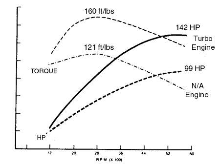
1) Significantly improve 2.2 engine output wile maintaining good gas mileage.
2) Take advantage of premium grade fuels while still running well on lower octane's.
3) Meet existing durability criteria.
4) Maintain maximum commonality with existing 2.2 in design and manufacture.
5) No unique service requirements.
New and redesigned components
Cylinder block-
Two bosses had to be added to existing casting to accommodate the turbocharger installation; One was the oil drainback at rear of the casting, the other was the mounting point for the intermediate shaft bearing bracket for the equal length driveshafts. Strengthening ribs were also added between the freeze plug locations for future power increases. It also allowed Chrysler to cast the bore walls thinner saving .6 pounds in the over casting.
Bearings-
Bi-metal bearings were chosen and tolerances were tightened up to better control oil pressure.
Cylinder head gasket-
Steel core asbestos construction with mild steel rings around the cylinder bores. Testing showed that the bore sealing rings had to be made thicker for better sealing and this improvement was passed on to the naturally aspirated engines as well.
Cylinder head cover-
New die cast aluminum cover & filler cap was done to enhance underhood appearance. An internal oil baffle was used doing away with the need of an separate external assembly.
Pistons-
8.1:1 ratio was used as an aid to controlling detonation when low octane fuel was used. The lower ratio allowed sufficient control of detonation without resorting to excessive spark retard which would resulted in exhaust temperatures exceeding 1652F which was the maximum limit for acceptable turbine housing durability. Cast and forged pistons were tested and cast were found to provide reasonable durability without the high cost of forged casting. The shape of the piston was carefully designed to minimize engine noise during cold startup and operation. This was critical because the detonation sensor can "hear" piston noise in certain rpm ranges and allowances in the engine control software had to be made under these conditions. Piston pin contact area was made 48% larger due to higher combustion pressures generated by turbocharger and oiling slots were also incorporated into the pin bore to prevent scuffing. Rings were similar to N/A rings except for a full face chrome treatment to prevent wear and a slight change in ring profile.
Camshaft-

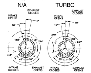
A cam was chosen for good low speed, low boost operation to minimize lag effects.
Valvegear-
Intake and exhaust valves were upgraded to better materials- Intake valve used SIL-1 instead of 1541 steel and the exhaust valve used a Inconel 751 head vs. 21-2N. Valve spring pressures were upgraded to 104 lbs closed & 175 lbs open which were excess of what was needed for 6650 engine shut off.
Lubrication system-
1) Oil pressure relief
spring was increased 10 psi.
2) Bearing tolerances were tightened.
3) 5 quarts oil specified helped lower oil temperatures.
4) Common oil pump for Turbo and N/A engines could now be used reducing parts
numbers.
Intake-
New sand cast aluminum intake manifold with small plenum volume and short 94 mm runners was chosen for compact installation and good throttle response.
Exhaust manifold-
Made of high silicon nodular cast iron with no branch pairing like the N/A manifold for compact installation. It was 1.5 mm thicker then N/A manifold to pass durability testing and tie bars between runners were tried and discontinued due to runner warping problems.
EGR system-
It had one and was needed at the time and the turbo compressor housing wasn't damaged by where it was located.
Turbocharger-
Garrett model number: TB0335 was selected with several unique revisions for use in Chryslers 2.2 engine. Specs are as follows: 50 trim compressor in .42 A/R housing, 69 trim turbine with .48 housing. With this combination they were nearly able to deliver full boost by 2000 rpm. (7.2 psi)

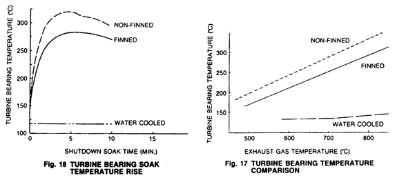
Extensive time was spent on turbocharger durability testing and several methods were tried including an air cooled housing before water cooling was selected. While the finned housing was good for a modest 90F temperature drop the water cooled center section was good for 351F! Another item that was changed to increase durability was the adoption of aluminum turbo bearings. One side benefit of using the engine coolant to cool the turbo housing was a modest reduction in oil crankcase temperatures which allowed the elimination of a planned oil cooler saving money, weight & complexity.
Engine control system
Throttle body-
42 mm blow through unit located upstream of the compressor due to packaging constraints incorporating AIS, TPS and various vacuum nipples. There was one problem with using this arrangement- High intake manifold air temperature due to recompression of the air charge BUT it also allowed for a minimum of turbo lag.
Logic Module-
Based on Motorola 6801U4 microprocessor with 6K ROM, 2K external PROM and 192 byte of RAM.
Fuel system-
MPI system using 269 cc.min injectors operating at 55 psi up to 6650 rpm. Injectors are batch fired in 2 pairs- cylinders 1 & 2 and cylinders 3 & 4. This also made it easy to selectively enrichen cylinders 3 & 4 because they ran leaner due to their proximity to the intake manifold air entrance.
Fuel Scheduling-
The basic injector pulsewidth is based on speed density principle- Engine RPM x MAP x Intake charge temp. Open loop pulsewidth considers two fundamental engine breathing characteristics- airflow variation with map and variation of volumetric efficiency with engine speed. pulsewidth is determined simply by multiplying the Map based value by the volumetric efficiency factor. In the software architecture these values are determined by functional calculation rather than interpolation of look up tables. Additional corrections are also used for charge air temperature, cold start, battery voltage and acceleration enrichment. One of the problems of turbo engines is it's need for overfueling at high engine loads as a means for controlling exhaust gas temperatures so as not to exceed the maximum allowed component spec of 1650F. Fuel-air ratios .095-1.0 volts are required to satisfy this requirement. Note that the optimum ration for maximum power is significantly leaner then .095 typically .075-.080 A lot of time was spent finding a proper balance between acceptable fuel economy and optimum mixture for durability of exhaust components and pistons.
Detonation sensor-
A narrow band piezoelectric accelerometer is mounted in the intake manifold which is tuned to detect noise in the 6.15 kHz range. The computer compares the sensors output with the known frequencies that the engine is know to vibrate at. If the computer determines what it is detecting isn't normal background noise it starts retarding the timing in 4.2 degree increments (up to a maximum of 14.7 degrees) till the knocking ceases. This allows the 2.2 engine to operate on lower octane gasoline without engine damage.
Conclusion-
1) Improved output of 2.2 engine.
2) With redesign of key base engine components all durability criteria met.
3) Detonation sensor system allows outstanding performance with hi-octane fuel and still allow satisfactory operation with normal grades.
4) With water-cooled centersection no unusual idle time nor maintenance is required.
5) Maximum commonality between other Chrysler 4-cylinders.