By Andrew E. Johnston
Technical Support Manager
Garrett / Bendix Heavy vehicle Systems Group
INTRODUCTION
The Garrett Variable Nozzle Turbo (VNT) is one of the most advanced and interesting turbochargers that has ever been offered in production. Unfortunately the first production application of a VNT on the Shelby CSX was shorter than expected, and Garrett was left with around 1200 of these turbos. Garrett decided to make these discontinued units available as surplus at a reduced price for race and custom installations. This article discusses some basic theory and application notes for this unit.
BASIC THEORY
Matching a turbocharger or supercharger to an engine that only runs at one speed and load would be easy. Designing a system that will achieve the optimum boost pressure under all conditions is much more challenging. Ideally, the boost could be controlled smoothly and efficiently at any speed or load. Achieving this goal requires an air compressor with a variable power source.
Superchargers are limited in this respect because they must obtain their power directly from the crankshaft.
This has two disadvantages:
1) They are directly linked to engine speed, not boost requirements, making it difficult to turn on "half way" at part load.
2) It consumes crankshaft power directly (typically 30-60
% of the engine output hp!)
Mechanical variable speed drive systems have been tried, but they are expensive, big, hard to control, and inefficient. Simple superchargers systems are typically belt driven and are controlled by a combination of on/ off switching and throttling, either of which are a compromise under part load conditions.
Turbochargers on the other hand, obtain power to drive the compressor from a small gas turbine that extracts energy from the hot exhaust. This is much more efficient than taking power from the crank directly because it is using thermal energy that would otherwise be wasted. The additional backpressure only consumes a fraction of the power that would have been required from the crankshaft The high speed of the turbine allows the use of an efficient high speed centrifugal compressor without the need for expensive gears or drive systems.
The turbine also has an important advantage because it is not directly linked to engine speed. The turbine power output tends to follow engine load, which is one of the reasons why most turbo diesel engines do not need any boost limiting controls. The compressor power, and therefore boost, can be easily controlled by changing the turbine power if desired. One way to control turbine power is with a wastegate. A wastegate is simply a valve that allows some of the exhaust to flow around the turbine instead of through it. This limits the turbine power at high speed when more exhaust energy is available than needed to drive the compressor. A wastegated system allows the use of a smaller turbine that is sized to make boost at low engine speed.(i.e. the wastegate is closed) The wastegate will prevent the turbo from overboosting at high speed as would otherwise occur with a small turbine.
This system offers smooth and simple
control, but still not optimum. The exhaust energy bypassed around the
turbine is wasted which is why they are called wastegates. At high speed
a turbine with a larger nozzle could use all the exhaust flow and make
the same power with less exhaust backpressure. The ideal system would have
an adjustable turbine nozzle that acted like a small turbine for fast response
at low speeds and a large turbine for maximum power and efficiency at high
speeds . An adjustable turbine could also be opened to minimize backpressure
when boost is not needed. This would provide the ideal boost with minimum
exhaust backpressure under all conditions.
THE GARRETT VNT25
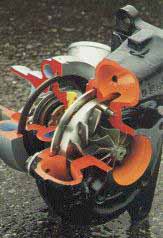
Garrett has developed a turbocharger
that does this. Instead of using one nozzle to accelerate the exhaust gas
towards the turbine wheel, it has a ring of 12 variable vanes. As the vanes
are rotated, they change the area of the nozzles that the exhaust must
pass through. The smaller the nozzle, the faster the gas velocity, the
more turbine power, the more boost. At the other extreme the vanes can
open fully when boost is not needed, with the resulting reduction in exhaust
restriction. The concept of the VNT has been around for a while, the trick
was to make one where the vanes would not stick when run for thousands
of miles without lubrication in a hot exhaust environment. Garrett spent
considerable time in r&d to arrive at the special combination of high
temp materials and manufacturing processes for the vanes and mechanism
to ensure reliable operation.
The VNT is mated with a low inertia rotating group and an efficient centrifugal compressor to achieve the goal of a truly adjustable boost system. In addition the system efficiency is improved at high speed due to the reduction in backpressure compared to a wastegated system.
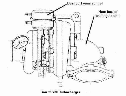
CHRYSLER APPLICATION INFORMATION
From an application standpoint, this turbo was used on the high output intercooled 2.2 liter four cyl. rated at 175 hp. The Chrysler engineers utilized the engine computer to take advantage of the additional control afforded by the VNT. The computer controlled the vanes by adjusting the pressure fed to the spring and diaphragm actuator. This system used a standard catalytic converter and exhaust system. The turbo limited boost by action of the vanes and did not use a wastegate.
CUSTOM APPLICATIONS
So, What engines are candidates for a VNT 25? The answer is not so much engine size, but power. This turbo should work on an engine that can produce 150-200 hp with 8-15 lbs of boost. I am aware of a 1600cc VW installation that is very responsive. Twin VNT's on a 400 hp Porsche should be outrageously more driveable than the stock big single turbo. Another candidate for a twin would be a Buick 3.8 liter V6. This turbo should also work on high rpm 1 liter motorcycles, but the turbine housing is fairly large from a packaging standpoint. Remember that these application suggestions are just that, not guarantees. These units have standard late model Chrysler turbine and compressor housing connections and use standard Chrysler gaskets. As far as using the VNT on a custom application, the flange dimensions and bolt patterns are not the same as any other turbo, but adapters can be made with the dimensions shown
OIL SUPPLY
This turbo needs .3 gpm of oil @ 30 psi. minimum at full power. Any oil that you can use in the engine will work for the turbo. The oil drain uses one bolt and seals with an O ring. A flat flange with a gasket will also work. A .5 inch minimum inside diameter oil drain is recommended and must be within 30 degrees of vertical with no "sink traps" that will allow oil to puddle.
CARBON SEALS
The unit uses a carbon seal and therefore be used with a carburetor upstream in a draw through installation,although the Chrysler was fuel injected. Except for the VNT turbine, this unit is very similar to a standard Garrett T25. The compressor, bearings and seals are interchangeable with T25 turbos.
WATER CONNECTIONS
The water cooling is intended for passenger car applications where the turbo is bolted to a heavy cast manifold withlittle airflow and many miles of stop and go service. The water cooling is not needed on a race car that isn't driven daily. Likewise, the water is not needed when the turbo is mounted on headers that don't store heat like a casting can. The water fitting is designed to mate with a steel tube flare nut. These can be removed and a different adapter can be threaded directly into the pipe threads and in the housing. Remember that the water is only for cooling during shutdown, the oil cools the bearings when the engine is running. When the engine is shutdown the heatstored in the cast exhaust manifold "soaks back" into the turbo causing the water in the center housing to boil.
When this happens it is important that the bubble that forms can escape upwards causing water to flow in from below and allowing the cycle to repeat itself. The upper hose should connect to the engine at a higher point than thelower water connection. The water flow direction while the engine is running is not important. It is when the engine stops that the boiling occurs.
TEST INSTALLATION AND VNT CONTROL
To determine the ease of controlling the actuator and to discover any installation problems in general, the author installed a VNT25 on his sandrail (Dunebuggy). The engine is a 2 liter German Ford. To keep the installation assimple as possible, the turbo was mounted on an old Roto-Master cast iron manifold that was intended for a T04B. Drilling the bolt holes out to 9/16" allowed the turbine to fit 3 of the 4 bolt holes and sealed acceptably for the test. The turbo pressurized a Motorcraft 121 two barrel carb in a simple "blow through" configuration. The pressure side (small tube) of the VNT actuator was connected to the hose fitting in the compressor housing.
The results were instant boost and easy wheelstands in 1st and 2nd gear. The vanes were closed at idle and it was very quiet, even without a muffler. The VNT limited the boost to 12 psi without any further controls during thequick " around the block" bonzai runs. (This control point is a function of engine size and flow and may be different for your application.
The addition of paddle tires and some steep dunes, however, changed things. The engine was not fully loaded onsuch a light vehicle on flat pavement. On a steep incline the boost would rise to over 20 psi as the engine became fully loaded. The solution was to install a conventional wastegate to control boost when the flow range of the VNT was exceeded. This is recommended for all VNT applications.
BOOST CONTROLS
Chrysler did not need a wastegate because the backpressure of the stock exhaust limited turbine power. TheSandrail used a very low backpressure 2.5" exhaust system. The Sandrail installation simply ran a hose from the compressor housing to the pressure port of the actuator. Do not make the mistake of assuming that the larger 1/4" port is for pressure because it is the same size as the fittings on the compressor housing. The 1/4" port is for vacuum. The smaller 3/16" port is for pressure. Pressurizing the vacuum port forces the vanes closed at all times.
They will eventually plug up with carbon, causing the " potato in the tailpipe" effect. If your engine runs poorly or won't start again after your first test run, check the actuator hoses. The boost setting can be mechanically adjustedwithin a limited range by shortening the rod length. Make sure the diaphragm does not bottom out before reaching the full stroke. It can also be adjusted with an electronic adjustable boost control system that is designed to control a conventional wastegate.
A pressure regulator can also be used as a "boost over boost" control to raise the actuator pressure control point just as it is used on a wastegate. In a nutshell you run a controlled amount of boost to the "wrong" side of theactuator to cancel out part of the pressure on the boost side. Each psi put on the back of the diaphragm raises the boost setting by 1 psi and so on. This is plumbed by hooking up the actuator pressure port to a boost signal (i.e. the fitting on the compressor housing) directly as usual. Then hook up a second from the same boost signal to a pressure regulator and then to the vacuum side of the actuator. Setting the pressure regulator to 1 psi raises the boost `1 psi etc...
In an off road or race only application this simple system will suffice. As a minimum a " part throttle open" controlcan be easily achieved by connecting manifold vacuum through a check valve to the vacuum side ( big tube) of the actuator. The check valve is to block boost. To prevent any pressure from being trapped between the check valve and the actuator, a .030" bleed orifice to atmosphere should be used. This will open the nozzles when vacuum is present at idle and part throttle.
This has some important benefits:
1. It cycles the vanes every time the throttle
is depressed which helps them stay free of carbon.
2. It prevents excessive EGR due to higher then normalbackpressure
which affects idle quality.
3. It improves fuel economy by eliminating backpressure
caused by the turbo.
4. It prevents part throttle boost which heats the intake
air unnecessarily.
5. It provides a more linear feel to the
throttle pedal position.
GENERAL INFORMATION
There are a few very important points concerning these turbos:
1) A common question is: Do you have one with a different compressor wheel, or A/R? The answer is no We only have this particular unit available. ( p.n. 465599-6)
2) These turbos have been discontinued and once the 1200 are gone that is it. Chrysler reportedly has quite a few for the Shelby's, but they may cost more when purchased through a dealer.
3) As far as emissions are concerned, this turbo is only legal on the 89 CSX, 90 Shadow, 90 Daytona, & Lebaron VNT's .END