The Mercury FAQ
This is a Mercury system FAQ page containing general information from Quantum3D and "how to" information for people looking to get a Mercury system operational. Since most people only have purchased a "brick" as it is fondly called several items are needed to get that brick up and rendering.
Items needed-
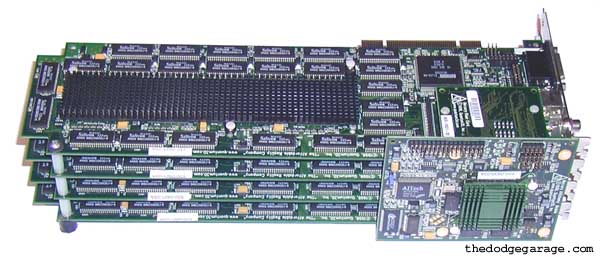
Complete brick- There are two different bricks out there, the early black PCB bricks with 100 mhz ram and the later green PCB bricks with 125 mhz ram. The brick must have all four connector cards and the AA module on top. There is black and green AA modules, but I have seen black bricks with green AA modules and there is two different known riser card part numbers. You cannot have a brick made up of mixed black and green 200SBi's or one made up of cards with different firmware revisions.
Intel BX/GX motherboard with four PCI slots- I'm told that the black bricks *REQUIRE* an Intel GX+ server board part number 721242-007. I don't know if this is true or not, that is the original part number used by Quantum3D for the Heavy Metal systems and what we are told. On the other hand the later green brick I own works just fine on a genuine Intel BX Seattle board with no problems at all. So if you have a choice the green brick is the way to go, of course sometimes we don't have a choice and the GX+ motherboards are fairly easy to find on Ebay.
Operating system- NT4 with service pack 3 or better. Windows 2000 works with a brick using the NT4 drivers but the control panel applet is missing. I'm trying to get this rectified now.
Floppy cable- To connect AA module to external Medusa PCB or other video adapter. Yes, it's just a floppy cable with one warning or two.
External VGA connector- Required as the video output connectors on the cards are as dead as a doornail since all rendering output is directed through the AA module up top. We show you how to make one or two =)
Medusa cable- Not required with one solution, required if you have original Medusa I/O PCB or looking to make something original.
Power Supply- Quality 400+ watt unit. I have a quality 350 watt unit here I'll be doing some testing with to see if it works. Merc's shipped from Quantum3D with PC Power & Cooling 400 and 425 watt units.
Proper ventilation- Merc bricks make great space heaters, the original rack mount units from Quantum3D have no less then 6 burly fans huffing and puffing away on the cards. Don't let your cards overheat!
Drivers & Documentation - Head over to the downloads page to grab drivers and documents for the GX+ motherboard and Hg brick NT4 drivers.
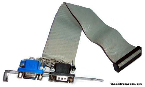
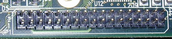
Video output ribbon cable (floppy cable) that runs from AA module to output PCB.
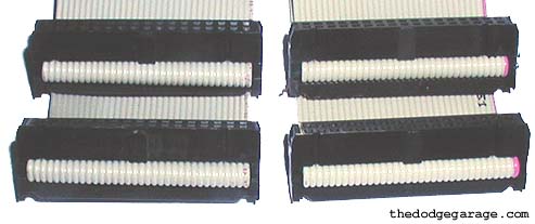
You need a floppy able with just two plugs, no twisted wiring, no blocked pin holes and they MUST be folded over at the plug connection. Some cables have the cable passing clean through without a double-back over the plug, I don't think this will do and rather not take the risk ;-)
Shown above is a Quantum3d Mercury cable on the right and a regular old floppy cable on the left. The only difference between the two is the Mercury cable was 13" long, the floppy cable 21". You can try running it at 21" but I would shorten to prevent possible signal loss. When the cables are lying on the table one connector should be facing up, the other facing down.
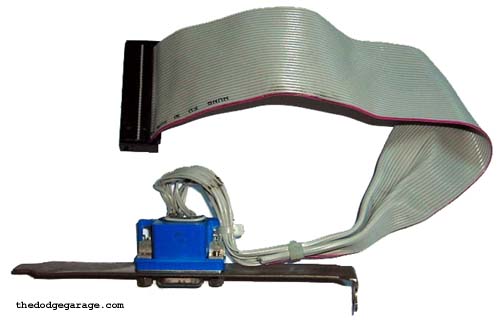
Video I/O Connector PCB for Medusa cable (solution one)
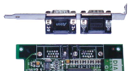
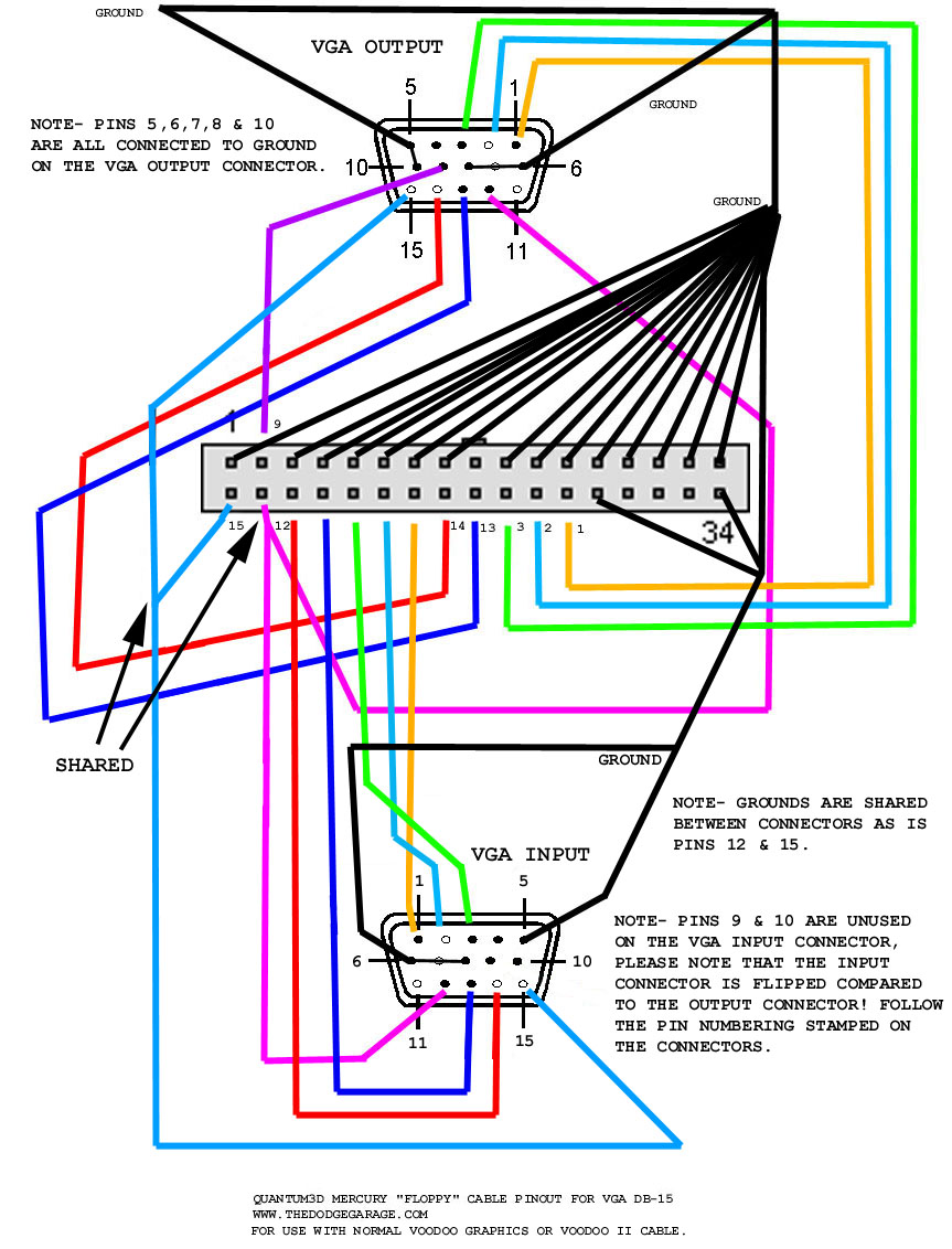
Solution one is so simple I'm kicking myself for not thinking of it before. The regular Quantum3D setup uses a Medusa cable with a 26 pin connector on one end and and two VGA input and output connectors on the other. The simple solution since Medusa cables & connectors are in short supply is to take the floppy cable and solder the appropriate wiring directly to a header backplate with regular VGA I/O sockets mounted and then you can use a regular Voodoo I or II pass through cable! You loose the TV out function (which seems disabled in the Mercury drivers anyway) or if your feeling saucy you can drill a hole below the VGA connectors and mount a RCA or S-video jack and hook the wiring up.
(Click for larger image in new window)
I did not bother tracing the wiring for the TV output since it is disabled but can tell you it would be floppy pins 28, 30 & 32. Two of the pins would be for the S-video output and the last would be for RCA out. Pin 17 of the floppy connector ends up on VGA pin number 11 which is odd as pin 11 is not used for anything on the VGA connector, I did not bother hooking it up for this reason.
Completed Version 2 connector with functional VGA 2D pass-through just like Voodoo Graphics or Voodoo II.
Version 1 with just VGA output (two monitors required, no pass-through) perfect for testing.
Video I/O Connector PCB for Medusa cable (solution two)
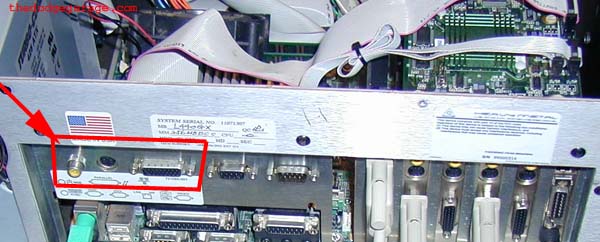
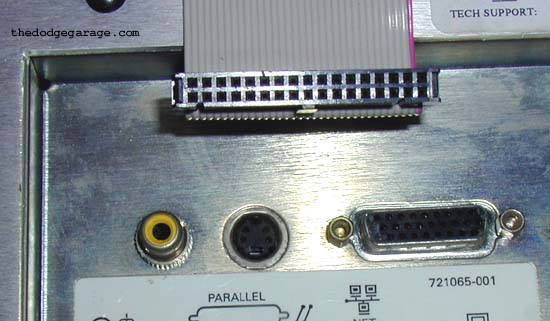
Highlighted area showing Medusa connection for video input/output.
Backside shot showing correct output PCB installed in case- Forget asking for Quantum3D for a new one!
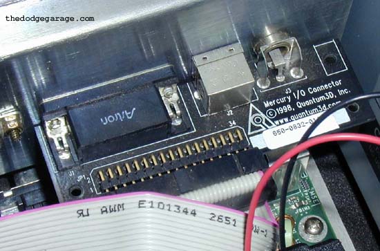
Close up of area and cable hanging over back of open case.
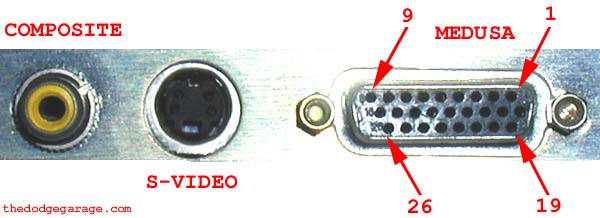
Medusa video output from AA module- Pinout was obtained by unplugging "floppy" cable from AA module and inserting a probe in each pin of the "floppy" connecter and checking the Medusa socket end mounted in the case to see where continuity was.
Pin one on the floppy connector is easy to find as it will have a small arrow on the connector pointing at it and you can also look at the top of the AAlchemy module where it's marked on the PCB.
| Floppy pin number | Medusa pin number | Notes |
| 1 | MULTI* | CASE GROUND |
| 2 | 6 & 14 | |
| 3 | 26 | |
| 4 | 4 & 15 | |
| 5 | MULTI* | CASE GROUND |
| 6 | 21 | |
| 7 | MULTI* | CASE GROUND |
| 8 | 20 | |
| 9 | MULTI* | CASE GROUND |
| 10 | 3 | |
| 11 | MULTI* | CASE GROUND |
| 12 | 2 | |
| 13 | MULTI* | CASE GROUND |
| 14 | 1 | |
| 15 | MULTI* | CASE GROUND |
| 16 | 25 | |
| 17 | 26 | |
| 18 | 24 | |
| 19 | MULTI* | CASE GROUND |
| 20 | 7 | |
| 21 | MULTI* | CASE GROUND |
| 22 | 8 | |
| 23 | MULTI* | CASE GROUND |
| 24 | 9 | |
| 25 | MULTI* | CASE GROUND |
| 26 | MULTI* | CASE GROUND |
| 27 | MULTI* | CASE GROUND |
| 28 | UPPER LEFT | S-VIDEO |
| 29 | MULTI* | CASE GROUND |
| 30 | UPPER RIGHT | S-VIDEO |
| 31 | MULTI* | CASE GROUND |
| 32 | RCA CENTER | COMPOSITE |
| 33 | MULTI* | CASE GROUND |
| 34 | MULTI* | CASE GROUND |
Pins 5, 10, 11, 12, 13, 16, 17, 18, 22 & 23 *of the Medusa connector* all run to case ground as does the RCA outer ring and the two lower pins of the S-Video connector.
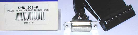
I plan on mounting a 26 pin socket (PAN PACIFIC DHS-26S-P PKGD HiDen 26PIN/F D-SUB SOL) and RCA jack hijacked from a dead Rush board on an old sound card backplate (the joystick port has the same pin to pin spacing as the Medusa connector) and soldering the ribbon cable one wire at a time to where they need to go on the socket.
After that it's a simple matter to screw it in an unused card slot location and hook the wiring up.
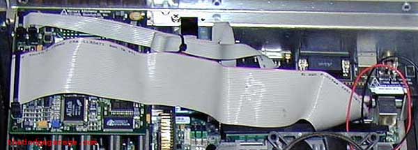
Overhead shot showing cable running from AA module to I/O PCB in case back on right.
Questions-
1) How can I tell if it is working or not?
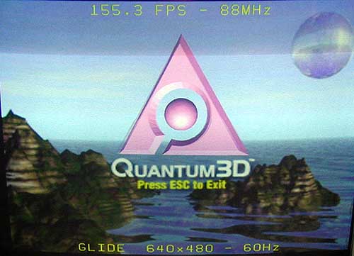
Answer- The lights dimming in the house were not your first clue?? All kidding aside the easiest way to tell if the brick is working correctly is to go into the graphics control panel, click on the Obsidian2 tab and click on Glide test. You should see the screenshot below on your monitor after a few seconds.
NOTE- If you don't have a loop-back cable for the sync-lock connectors the Glide test will hang if "sync to refresh" is checked off.
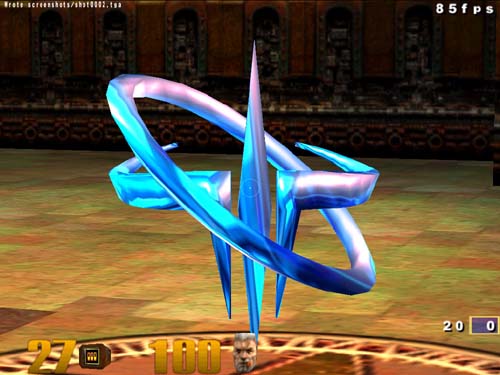
2) What games/programs run on Mercury?
Answer- Well so far I have run GLQuake, Quake II, Quake3test, Quake3-3dfx motion blur demo and Unreal. Pretty much any game that will run under Glide or OpenGL under Windows NT4 will work just fine. The screenshot below was taken at 1024 x 768 and downsized to 500 x375 to fit in the window frame and keep the page load reasonable.
3) How fast is Mercury?
Answer- I have not done any back to back benchmarks between Mercury and say a Voodoo II SLI rig but will do so in the near future once I get everything setup the way I want. The big attraction with Mercury isn't speed but the fact it does 4 tap rotated grid anti-aliasing in hardware. Any program you run automatically takes advantage of this feature! I'll try to get some screenshots but it's very difficult as every program I have tried so far does NOT capture the anti-aliasing in action. I suspect that the programs are pulling the image out of only one of the cards frame buffers and you are not seeing the whole picture.
4) How may different Heavy Metal systems did Quantum3D make?
Well the Mercury GX+ was top of the line till Heavy Metal AALchemy (VSA-100 based) was released and you could configure Mercury into a MAX system (four or more Mercurys in a swaplock ring) as well! Some Heavy Metal systems were software solutions, others had single 200SBi boards.
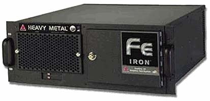
Heavy Metal Iron was software based (Information from Quantum3D press release) but supposedly Obsidian cards were an option. Notice the Quantum3D FAQ below mentions the H.M. Iron configuration, it states the Iron system *CAN* be configured with 200SBi's, not *WAS* configured.
Heavy Metal Cobalt was hardware assisted full scene edge anti-aliasing accomplished through technology licensed exclusively by Quantum3D from Spatial Labs™ I assume the system had a single 200SBi but could be wrong. (No other inforamtion)
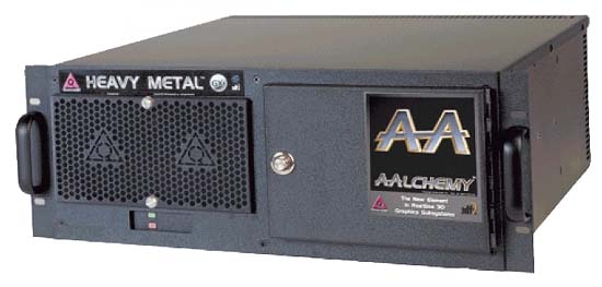
Heavy Metal Mercury was full hardware based, 200SBi's or Mercury brick.
Heavy Metal BX and GX+ are also listed in a later brochure, Quantum3d might have just been simplifying options. The BX system was listed as being available with 1-2 Ventana boards (Voodoo 3) *OR* 1-2 200SBi's.
The GX+ was listed as being available with 1-2 Ventana boards (Voodoo 3) *OR* 1-2 200SBi's. *OR* Mercury *OR* AAlchemy 4xxx or 8xxx.
I also suspect there was other Heavy Metal systems before AAlchemy- Quantum3D seemed pretty flexible about making anything the customer wanted to order.
Quantum3D Compiled FAQ (2-8-2000)
Q: What models of Heavy Metal™ are available?
A: There are two models available. The Heavy Metal™ Iron BX and Heavy Metal™ Mercury GX+ systems. The Heavy Metal™ Iron BX is a Quantum3D PCIG (Personal Computer Image Generator) with a motherboard based on the Intel BX Chipset. Its features include, SCSI, Single PCI Bus, AGP and ISA Buses. The system can be configured with multiple Obsidian2 200SBi accelerators. The CPU's can be single or dual PII/PIII variations. The Heavy Metal™ Mercury GX+ is a Quantum3D PCIG (Personal Computer Image Generator) with a motherboard based on the Intel GX+ Chipset. It's features include, SCSI, Dual PCI Buses, AGP and ISA Buses. The system can be configured with either multiple Obsidian¨2 200SBi accelerators or the Obsidian¨2 Mercury graphics sub-system. The CPU's can be single or dual PII/PIII variations. A built in AGP ATI graphics chipset provides 2D/3D acceleration (Incorrect- The GX+ has Cirrus Logic on board with no 3D features at all) directly from the motherboard. SCSI and Ethernet are also provided directly on the motherboard. The most significant difference between the BX and GX+ motherboards is the GX+ has the ability to utilize 2 PCI Buses. This means that the GX+ delivers the best graphics performance for the Mercury graphics subsystem and for multiple Obsidian¨2 200SBi accelerators.
Q: What is the Heavy Metal™ MAX system?
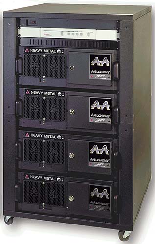
A: The Heavy Metal MAX are multi-channel Quantum3D system that consists of at least one Heavy Metal PCIG and a PC Host computer. These systems are typically delivered in a 19" rack. They include the PCIG Channels, Host Computer, 100Mbps Ethernet Hub, Keyboard, Mouse, Monitor, Raritan Switch, and Power supply.
Q: How is the Heavy Metal™ MAX system powered on?
A: The system can be powered on by depressing the switch closest to the bottom of the chassis. It is located behind the panel door.
Q: How is the Raritan switch used?
A: The computer switch enables control between multiple computers from only one monitor, keyboard, and mouse. After installing each of the systems to the computer switch, follow the common Hot key commands below: [ESC] = Quit Hot Key Mode [SCROLL LOCK] = Activate Hot Key Mode (Twice) [LEFT/RIGHT ARROWS] = Increment Channel Number
Q: How can the Raritan switch be reset to resolve problems with the lack of responsiveness or to terminate flashing lights being displayed?
A: The power to the Raritan switch is delivered through the keyboard connector. Removing the keyboard connector and powering down the entire rack's main power will reset the Raritan switch.
Q: What is the latest BIOS and drivers available for the Heavy Metal Iron BX system?
A: The latest BIOS is version 2.1 and is available from the Super Micro BIOS web page.
Q: What is the red button located in the front of the system used for?
A: The red button is not used and is just an extra switch that is included with the chassis. The power button is the black switch located closest to the bottom of the system.
Q: Why am I unable to power off the system when I depress the power switch?
A: The power switch must be depressed for (5) seconds to enable the motherboard power down feature.
Q: How many extra PCI and ISA slots are available using a standard configuration?
A: Every Iron BX system may be configured differently. Typically there are (2) PCI and (1) ISA available for adapters..
Q: Why is there an external cable with both connectors attached to the system?
A: The external cable is used for SwapLock. The top connector can be removed and attached to the top connector of a second system. Then the bottom connector of the second system can be attached to the top connector of the first system creating a SwapLock ring.
Q: What is Swaplock?
A: The SwapLock™ feature synchronizes the swapbuffer command across multichannel systems. This eliminates artifacts associated with lack of hardware frame synchronization. SwapLock™ synchronizes buffer swap and v-sync for every channel in a multichannel Heavy Metal PC Image Generator (PCIG).
Q: Can the Obsidian2 200SBi and Mercury graphics sub system be used together in a Swaplock ring?
A: Yes, However a Obsidian2 200SBi must be the MASTER of the Swaplock ring. This means that the Obsidian 200SBi must have the Master bubble checked in the Obsidian2 Display Propertied Tab.
Q: What should I do if the system fans power on but I am unable to power on the Heavy Metal Mercury BX system?
A: Remove the power cord to the system. Remove the cover to the chassis. Then disconnect the main power supply cables attached to the motherboard. Reconnect the power cord to the power supply. If the fans begin to spin up then the power supply is defective. If the fans do not spin up then there is an issue most likely with the motherboard or system. Power down the system and remove the power connections to the floppy drive, CD-Rom and any unnecessary peripherals. Power on the system to determine if this is a power consumption issue.
Q: What is the cause of the error "Boot Failure Insert boot diskette in A:" ?
A: This error is displayed due to the lack of Operating System files. This is typically caused by the loss of the IDE cable connection between the hard drive and the motherboard. Follow the steps below to diagnose and verify the root cause of the problem:
1. Confirm that the drive bay light on the hard drive removable tray is on when the system is powered up. If the light is not on and the number 0 is not being displayed then the tray may not be seated properly or the key on the tray may not be turned all the way disabling the drive.
2. Remove the cover to the system and physically verify the IDE cable connection between the motherboard and the hard drive tray. The IDE cable should be connected to the port on the motherboard. The other end of the cable is connected to the back end of the hard drive bay. Remove and re-seat the cable ends to confirm proper connections between the devices. Then power up the system to test if there is any occurrence of the error.
3. If multiple systems are available then remove the hard disk drive from the system giving the error and swap it with a hard drive from a known working system. This will verify that the drive has either failed or that the connection to the hard drive has failed.
Q: Where can I find product information about the Super Micro P6DBS motherboard?
A: There is product literature available from Super Micro.
(Written by Jim Rossi, 2000)
![]()